TM-9-2350-311-20-2 - Page 74 of 828
TM 9–2350–311–20–2
2–13
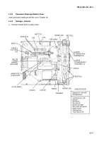
2–5.4
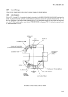
Internal Stowage
Follow internal stowed items location index for proper stowage of cab internal items.
2–5.5
Cable Diagrams
Refer to FO–1 through FO–4 for electrical/hydraulic schematics for M109A2/M109A3/M109A4/M109A5 howitzers. Ap-
pendix I, Hydraulic Schematic Symbols, provides hydraulic symbols as used on the hydraulic schematics. See FO–1 for
electrical schematics for M109A2/M109A3 howitzers and FO–2 for electrical schematics for the M109A4/M109A5 howit-
zers. See FO–3 for hydraulic system schematic for M109A2/M109A3 howitzers, and FO–4 for hydraulic system schematic
for M109A4/M109A5 howitzers.
INTERNAL STOWED ITEMS LOCATION INDEX
PROJECTILE
STOWAGE
(22rds.)
PROPELLANT STOWAGE RACK
M16 FUZE WRENCH
M18 FUZE WRENCH
STOWAGE
BOX
FLARE
BRACKET
ASSEMBLY
FLASHLIGHT
PHONE
ODDMENT TRAY
STOWAGE
BOX
M1A1
COLLIMATOR
PERISCOPE
BOX
CANTEEN HOLDER
FLASHLIGHT HOLDER
(IN M109A2/M109A3 MODELS)
Back to Top

