TM-9-2350-311-34-1 - Page 184 of 352
References
Tools
Equipment Conditions
Materials/Parts
INITIAL SETUP
TM 9-2350-311-34-1
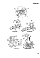
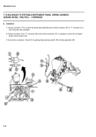
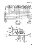
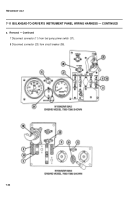
7-11 BULKHEAD-TO-DRIVER’S INSTRUMENT PANEL
WIRING HARNESS
This task covers:
a. Removal
b. Disassembly
c. Assembly
d. Installation
General mechanic’s tool kit (item 14, Appx C)
TM 9-2350-311-20-1
Electrical tape — black (item 25, Appx B)
Batteries disconnected (TM 9-2350-311-20-1)
Lockwashers (2) (item 37, Appx F)
Portable instrument panel removed (TM 9-2350-311-20-1)
Connector
Wire
No.
Electrical Lead To:
No.
1
2
3
4
5
6
7
8
9
10
11
12
13
14
Service headlight dimmer switch —
low beam
Service headlight dimmer switch —
high beam
Service B.O. IR headlight —
low beam
Service B.O. IR headlight —
high beam
Not used
Master switch circuit
B.O. marker light — front
Fuel level switch — right lower tank
Bilge pump switch — energizing circuit
Fuel level switch — right upper tank
Fuel prime switch
Stop light switch — light switch
Light switch — dimmer switch
Main light switch power lead
18
17
515
514
459
20
31
450
29
76
75
16
15
Connector
Wire
No.
Electrical Lead To:
No.
15
16
17
18
19
20
21
22
23
24
25
26
27
28
29
30
Main light switch — panel lights
40
Main light switch — B.O. marker rear
24
Main light switch — B.O. stop light
23
Main light switch — service stop light
22
Main light switch — service taillight
21
High beam indicator light
519
Not used
Light circuits
20-24
Driver’s dome light, auxiliary outlet, and trailer
receptacle
37-38
Auxiliary outlet and trailer receptacle
37
Not used
Driver’s dome light
38
Connector dimmer switch
Connector dimmer switch
Connector lighting switch
Master warning switch
459L
7-48
Back to Top


