TM-9-2350-311-34-1 - Page 189 of 352
TM 9-2350-311-34-1
NOTE
For quick guide to wire connector locations see paragraphs 7-2 and 7-3.
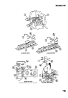
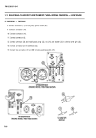
9 Disconnect seven connectors (29 8, 9, 10, 5,20, and 24) from driver's instrument panel.
NOTE
Screws are located inside of hull on rear bulkhead.
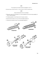
10 Remove two screws (40), two flat washers (41), and two Iockwashers (42) from left and right assemblies (43
and 44). Discard lockwashers.
11 Pull taillight assemblies (43 and 44) away from hull to expose connectors.
12 Disconnect three connectors (16, 18, and 19) from left taillight assembly (43).
13
Disconnect two connectors (16 and 17) from right taillight assembly (44).
7-53
Back to Top

