TM-9-2350-311-34-1 - Page 196 of 352
INITIAL SETUP
Applicable Configurations
References
Equipment Conditions
Materials/Parts
a.
Removal
TM 9-2350-311-34-1
7-12 POWER LEAD WIRING HARNESS (M109A2)
This task covers:
a. Removal
b. Disassembly
c. Assembly
d. Installation
Lockwashers (4) (item 34, Appx F)
M109A2
Tools
TM 9-2350-311-20-1
General mechanic’s tool kit (item 14, Appx C)
Batteries disconnected (TM 9-2350-311-20-1)
Electrical tape — black (item 25, Appx B)
Driver’s instrument panel removed (TM 9-2350-311-20-1)
Gasket (item 63, Appx F)
Lockwashers (4) (item 30, Appx F)
NOTE
Vehicles with engine model 7083-7396 use connector 5 for flame heater system.
Vehicles with engine model 7083-7391 use connector 5 for glow plug system.
Connector
Wire
No.
Electrical Lead To:
No.
Connector
Wire
No.
Electrical Lead To:
No.
1
2
3
4
5
6
Connector bulkhead (to slave start receptacle) 49
Connector accessory control box
10
Connector slip ring segment board
47
Connector hull lighting wiring harness
(interconnects with wire 15)
10
Connector starter switch/flame heater
switch circuit breaker (to wire 15) (engine model
7083-7396) or connector starter switch/glow
plug switch (engine model 7083-7391)
10
Connector fuel pump circuit
breaker (to wire 76)
10
7
8
9
10
11
12
Connector fuel prime pump switch
circuit breaker (to wire 588)
10
Connector master warning light/
engine instrumentation circuit
breaker (to wire 27)
10
Connector bilge pump switch circuit
breaker (to wire 450)
10
Connector auxiliary outlet/dome
light circuit breaker (to wires 37 and 38)
10
Connector slave start receptacle
49
Ground
50
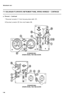
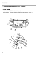
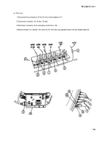
1 Disconnect six connectors (5 thru 10) from circuit breakers (13).
2 Disconnect connector (4) from wire 15 lead.
7-60
Back to Top


