TM-9-2350-311-34-1 - Page 200 of 352
TM 9-2350-311-34-1
7-12 POWER LEAD WIRING HARNESS (M109A2) — CONTINUED
a. Removal — Continued
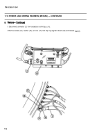
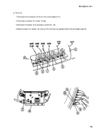
7 Disconnect connector (1) at driver’s compartment bulkhead.
8 Remove two plastic straps (26), four screws (27), and four washers (28) to release wiring harness.
9 Remove 11 plastic straps (29), 11 screws (30), and 11 washers (31).
b. Disassembly
Disassemble wiring harness leads (TM 9-2350-311-20-1).
c. Assembly
Assemble wiring harness leads (TM 9-2350-31 1-20-1).
d. Installation
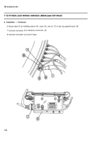
1 Install 11 plastic straps (29), 11 washers (31), and 11 screws (30).
2 Install two plastic straps (26), four washers (28), and four screws (27) to secure wiring harness.
3 Connect connector (1) at driver’s compartment bulkhead.
4 Connect slave start receptacle (19) to mounting plate (23) with four new Iockwashers (25) and four screws
(24).
NOTE
Wiring harness maybe removed from hull with slave start receptacle attached or
leads can be pulled out of receptacle with sockets as required. If wiring harness
removed is without receptacle, skip steps 5 and 6.
5 Install receptacle (19) as follows:
(a) Push receptacle (19) with mounting plate (23) from driver's compartment into battery compartment.
(b) Install new gasket (22), four new Iockwashers (21), and four screws (20) to battery compartment bulkhead.
7-64
Back to Top


