TM-9-2350-311-34-1 - Page 208 of 352
7-72
TM 9-2350-311-34-1
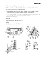
7-13 POWER LEAD (M109A2?M109A3) — CONTINUED
d. Installation — Continued
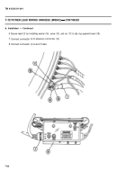
8 Connect connector (4) at wire 15 lead.
9 Connect five connectors (5 thru 9) to circuit breakers (11).
FOLLOW-ON MAINTENANCE:
NOTE
Install driver's instrument panel
(TM 9-2350-311-20-1)
Connect batteries (TM 9-2350-311-20-1)
7-14 POWER LEAD (M109A4/M109A5)
This task covers:
a.
d.
Removal
b. Disassembly
c. Assembly
Installation
M109A4/M109A5
Tools
General mechanic’s tool kit (item 14, Appx C)
Electrical tape — black (item 25, Appx B)
Lockwashers (17) (item 35, Appx F)
TM 9-2350-311-20-1
Batteries disconnected (TM 9-2350-311-20-1)
Driver’s instrument panel removed (TM 9-2350-311-20-1)
Back to Top

