TM-9-2350-311-34-1 - Page 214 of 352
TM 9-2350-311-34-1
SECTION Il. HULL ELECTRICAL COMPONENTS
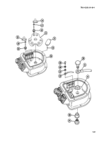
7-15 RECTIFIER (M109A2/M109A3)
This task covers:
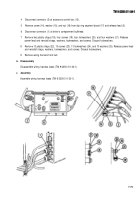
a. Disassembly
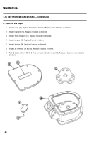
b. Inspection and repair
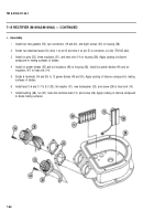
c. Assembly
M109A2/M109A3
Tools
General mechanic’s tool kit (item 14, Appx C)
Multimeter (item 16, Appx C)
Soldering gun (item 11, Appx C)
Acetone solvent (item 1, Appx B)
Electrical tape — black (item 25, Appx B)
Gaskets (2) (item 44, Appx F)
Lockwashers (3) (item 24, Appx F)
Preformed packing (item 49, Appx F)
Pressure-sensitive tape (item 26, Appx B)
Sealing compound (item 19, Appx B)
Silicone compound (item 22, Appx B)
Solder (item 23, Appx B)
Solder flux (item 24, Appx B)
References
TB SIG 222
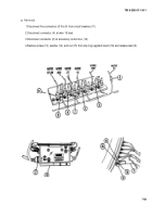
LEGEND
1 Power diode assembly CR-1
2 Power diode assembly CR-2
3 Power diode assembly CR-3
4 Power diode assembly CR-4
5 Power diode assembly CR-5
6 Power diode assembly CR-6
7 Capacitor C-1
8 Capacitor C-2
9 Capacitor C-3
10 Capacitor C-4
11
12
13
14
15
16
17
18
19
20
Capacitor C-5
Capacitor C-6
Heat sink terminal
Heat sink
Capacitor C-7
Terminal E-3
Terminal E-2
Terminal E-1
Connector J-1
Connector J-2
NOTE
Point of symbol indicates direction of conventional current flow. Power diodes consist
of two diodes and one terminal.
7-78
Back to Top


