TM-9-2350-311-34-1 - Page 218 of 352
TM 9-2350-311-34-1
7-15 RECTIFIER (M109A2/M109A3) —
CONTINUED
a. Disassembly — Continued
NOTE
There are two power diodes per power diode assembly CR-1 thru CR-6.
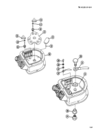
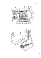
10 Remove three terminals (34) and three insulators (47) from three power diodes assemblies (4, 5, and 6).
Unsolder at diode poles to remove terminals (TB SIG 222).
11 Remove three terminals (35) and three insulators (46) from three power diode assemblies (1, 2, and 3).
Unsolder at diode poles to remove terminals (TB SIG 222).
12 Unscrew six power diodes (49) from heat sink (14).
13 Unscrew six power diodes (50).
14 Remove heat sink (14), three insulators (51), and six pins (52).
15 Unsolder two electrical leads (53) (wire 1 on pin B and wire 3 on pin E) from connector J-2 (20) (TB SIG 222).
7-82
Back to Top


