TM-9-2350-311-34-1 - Page 226 of 352
TM 9-2350-311-34-1
7-16 RECTIFIER (MI 09A4/M109A5) — CONTINUED
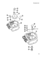
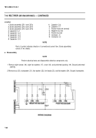
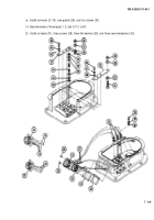
LEGEND
1 Diode assembly CR-1 and CR-4
9
2 Diode assembly CR-2 and CR-5
10
3 Diode assembly CR-3 and CR-6
11
4 Capacitor C-1
12
5 Capacitor C-2
13
6 Capacitor C-3
14
7 Capacitor C-4
15
8 Capacitor C-5
Capacitor C-6
Capacitor C-7
Positive heat sink terminal
Negative bus bar
Positive bus bar
Connector J-1
Connector J-2
NOTE
Point of symbol indicates direction of conventional current flow. Diode assemblies
consist of two diodes.
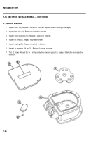
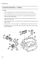
a. Disassembly
NOTE
Perform electrical tests and disassemble defective components only.
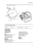
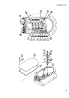
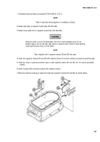
1 Remove eight screws (16), eight flat washers (17), cover (18), and preformed packing (19). Discard preformed
packing.
2 Remove nut (20), lockwasher (21), flat washer (22), five leads (23), and flat washer (24). Discard Iockwasher.
7-90
Back to Top


