TM-9-2350-311-34-1 - Page 231 of 352
TM 9-2350-311-34-1
b. Inspection and Repair
1
2
3
4
5
6
7
8
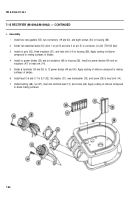
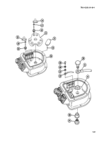
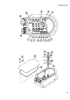
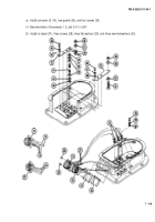
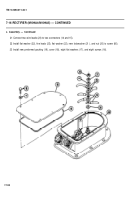
Inspect cover (18). Replace if cracked or distorted.
Inspect housing (56). Replace if cracked or distorted.
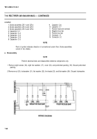
Test three diode assemblies (1, 2, and 3) for continuity (para 3-3). Replace if defective.
Inspect two connectors (14 and 15). Replace if pins are broken. Resolder leads if loose (TB SIG 222).
Inspect capacitor boards (55 and 59). Replace if boards are cracked or broken. Check for loose or missing
terminals. Replace as required.
Test capacitor (4) with red lead of multimeter on one capacitor terminal and black lead of multimeter on other
capacitor terminal. Multimeter should show continuity, then infinity (00). If only continuity is shown, replace
capacitor assembly.
Reverse multimeter leads on capacitor (4) and repeat step 6.
Repeat test procedure (steps 6 and 7) for capacitors (5 thru 9) and capacitor C-7 (10).
7-95
Back to Top


