TM-9-2350-311-34-1 - Page 230 of 352
TM 9-2350-311-34-1
7-16 RECTIFIER (M109A4/M109A5) — CONTINUED
a. Disassembly — Continued
13
14
15
16
17
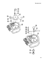
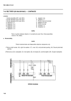
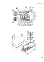
Remove six screws (53), six Iockwashers (54), and three diode assemblies (1, 2, and 3). Discard Iockwashers.
NOTE
Capacitor boards are secured to housing with pressure-sensitive tape. Remove only if
necessary.
Remove capacitor board (55) from housing (56).
Unsolder three electrical leads (57) from capacitor board (55) (TB SIG 222).
Unsolder lead (58) from capacitor board (59) (TB SIG 222).
Disassemble all rectifier electrical leads as required (TM 9-2350-311-20-1).
7-94
Back to Top

