TM-9-2350-311-34-1 - Page 234 of 352
7-98
TM 9-2360-311-34-1
7-16 RECTIFIER (M109A4/M109A5) — CONTINUED
c. Assembly — Continued
8
9
10
11
12
13
14
15
16
17
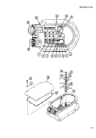
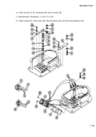
Apply coating of silicone compound to mating surfaces and install three diode assemblies (1, 2, and 3), six new
Iookwashers (54), and six screws (53). Torque screws to 20-23 lb-in. (2.3-2.6 N-m)
Install two nuts (45), two new lockwashers (44), and two washers (43) to ground terminal (38).
Install ground terminal (38) and secure by tightening bottom nut (45). Do not tighten top nut (45).
Install negative and positive bus bars (12 and 13), six new Iockwashers (42 and 48), six flat washers (41 and
47), and six screws (40 and 46). Torque screws to 20-30 lb-in. (2.3-2.6 N-m).
Install new Iockwasher (52), flat washer (50), screw (51), and nut (49) on positive bus bar (13).
Install two leads (39), new Iockwasher (37), and nut (36) at ground terminal (38). Tighten nut (36) and top nut
(45) against negative bus bar (12) to secure contact.
Install three leads (35) to connector J2 (15) and five leads (34) to connector J1 (14).
Apply sealing compound to threads of eight screws (25 and 32).
Install connector J1 (14), new gasket (33), and four screws (32).
Connect two wire leads 4 and 5 (27) to connector J2 (15).
Back to Top


