TM-9-2350-311-34-1 - Page 222 of 352
TM 9-2350-311-34-1
7-15 RECTIFIER (M109A2/M109A3) — CONTINUED
C
. Assembly
1
2
3
4
5
6
7
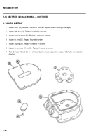
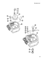
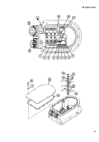
Install two new gaskets (55), two connectors (19 and 20), and eight screws (54) to housing (58).
Solder two electrical leads (53) (wire 1 on pin B and wire 3 on pin E) to connector J-2 (20) (TB SIG 222).
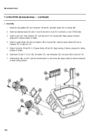
Install six pins (52), three insulators (51), and heat sink (14) to housing (58). Apply coating of silicone
compound to mating surfaces of diodes.
Install six power diodes (50) and six insulators (48) to housing (58). Install six power diodes (49) and six
insulators (47) to heat sink (14).
Solder 6 terminals (34 and 35) to 12 power diodes (49 and 50). Apply coating of silicone compound to mating
surfaces of diodes.
Install lead C-6 and C-7 to E-3 (32), flat washer (31), new Iockwasher (30), and screw (29) to heat sink (14).
Install bushing (28), nut (27), heat sink terminal lead (13), and screw (26). Apply coating of silicone compound
to diode mating surfaces.
7-86
Back to Top


