TM-9-2350-311-34-1 - Page 62 of 352
TM 9-2350-311-34-1
4-2 REMOVAL AND INSTALLATION OF ENGINE- AND TRANSMISSION-RELATED
COMPONENTS — CONTINUED
a. Removal — Continued
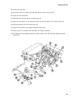
7 Remove screw (15), flat washer (16), Iockwasher (17), and nut (18) at mounting bracket (19) to release
tachometer cable (20) and speedometer cable (21 ) from mounting bracket.
8 Install screw (15), flat washer (16), Iockwasher (17), and nut (18) to mounting bracket (19).
9 Disconnect tachometer cable (20) from engine near generator.
10 Remove speedometer cable (21) and tachometer cable (20).
11 Disconnect four electrical connectors (22 thru 25).
12 Remove two screws (26), two Iockwashers (27), and engine disconnect bracket (28).
13 Install two screws (26) and two Iockwashers (27).
14 Remove nut (29) and sleeve (30) and disconnect primary filter-to-engine-driven fuel pump tube (31 ).
15 Remove two screws (32), two flat washers (33), two Iockwashers (34), two nuts (35), and primary fuel filter
(36). Discard Iockwashers.
16 Disconnect elbow (37) from engine-driven fuel pump (38).
17 Remove three screws (39 and 40), three flat washers (41 and 42), three nuts (43 and 44), and three tube
clamps (45 and 46).
18 Remove screw (47) and tube clamp (48). Install screw to transmission housing (14).
19 Remove primary fuel filter-to-engine-driven fuel pump tube (31 ).
4- 6
Back to Top


