TM-9-2350-311-34-1 - Page 66 of 352
WARNING
TM 9-2350-311-34-1
4-2 REMOVAL AND INSTALLATION OF ENGINE- AND TRANSMISSION-RELATED
COMPONENTS — CONTINUED
b. Installation
1
2
3
4
5
6
7
8
9
10
11
12
13
14
15
16
17
Do not smoke or use open flame when working on fuel systems. An explosion may
occur, causing severe injury or death.
Assemble powerplant (para 4-3).
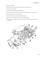
Install two hose clamps (75) to coolant main tube-to-bypass thermostat housing connector hose (80).
Attach coolant main tube-to-bypass thermostat housing connector hose (80) and tighten two hose clamps (75).
Install clamp (79), new Iockwasher (78), and screw (77).
Install two elbows (73) at crossover tube (74).
Install two hoses (72) and two hose clamps (71 ) to two elbows (73).
Install two hose clamps (68) to hose connector (69).
Connect hose connector (69) to coolant pump (70) and tighten two hose clamps (68).
Connect surge tank-to-coolant main tube hose (66) to surge tank (81) and tighten hose clamp (65).
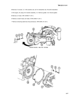
Install secondary fuel filter (64).
Install plug (63).
Install two nuts (62), two new Iockwashers (61), two flat washers (60), and two screws (59).
Install two tubes (57 and 58).
Install three flat washers (55) and three screws (54) and tighten three clamps (56).
Connect elbow (53) to engine-driven fuel pump (38).
Install adapter (51 ) to engine connector (52).
Install two adapters (49) to two secondary filter elbows (50).
4-10
Back to Top


