TM-9-2350-311-34-2 - Page 320 of 552
TM-9-2350-311-34-2
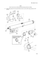
6-11 EQUILIBRATED ELEVATION MECHANISM ASSEMBLY - CONTINUED
d. Assembly - Continued
5
6
7
8
9
10
11
12
13
14
15
NOTE
Steps 5 through 15 pertain to unmodified equilibrated elevation mechanism assembly.
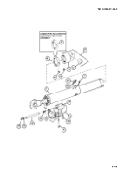
Lubricate two headless straight pins (80), new seal ring (87), new preformed packing (85), new split ring
(86), and four new preformed packings (88) with hydraulic fluid and install securely on front cylinder bearing
(84).
Insert two 5/16 inch 24 UNF cap screws (77) through bearing guide (75) and tighten into front cylinder bear-
ing (84).
Slide bearing guide (75) into cannon equilibrator (37) from the front end. Have an assistant place and hold
three key segments of wiper ring (89) in center groove (103) while front cylinder bearing (84) is pushed into
place. Be careful that new preformed packing (85) on front cylinder bearing is not cut or damaged as it
passes over oil port (104). Observe new preformed packing through oil port.
Remove two 5/16 inch 24 UNF cap screws (77) from front cylinder bearing (84) and bearing guide (75).
Withdraw bearing guide (75) from cannon equilibrator (37).
Lubricate new seal ring (83), new preformed packing (81), and new split ring (82) with hydraulic fluid. Install
on rear cylinder bearing (73).
Place rear cylinder bearing (73) on bearing guide (75).
Insert two 1/4 inch 28 UNF guide rods (105) through bearing guide (75), rear cylinder bearing (73), and rear
of cannon equilibrator (37). Screw two 1/4 inch 28 UNF guide rods into mating holes of front cylinder bearing
(84) to ensure proper alinement of pin and cap screw holes in front cylinder bearing and rear cylinder bear-
ing.
Slide rear cylinder bearing (73) into cannon equilibrator (37).
Remove bearing guide (75) by unscrewing two 1/4 inch 28 UNF guide rods (105).
Apply sealing compound to two cap screws (72) and install through rear cylinder bearing (73). Torque cap
screws to 9 Ib-ft (12 N·m).
6-58
Back to Top


