TM-9-2350-311-34-2 - Page 326 of 552
TM 9-2350-311-34-2
6-11 EQUILIBRATED ELEVATION MECHANISM ASSEMBLY - CONTINUED
d. Assembly - Continued
40
41
42
43
44
45
46
47
48
49
50
51
52
53
54
55
56
6-64
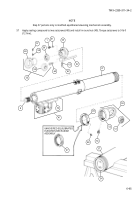
Place cap (65) on elevating piston rod (8).
Lubricate end cap guide tool (not shown) with hydraulic fluid and install over elevating side of elevating pis-
ton rod (8). Position cap (65) on end cap guide tool and push into place on cannon equilibrator (37) attach-
ing tube coupling (42) to bracket assembly (32).
Apply sealing compound to threads of 12 cap screws (64). Install 12 cap screws, securing cap (65) to can-
non equilibrator (37). Torque 12 cap screws to 90 Ib-ft (122 N·m).
Remove end cap guide tool (not shown).
Install new preformed packing (61) and bleeder valve (1) on cap (65).
Install new preformed packing (63) and plug (62).
NOTE
End rod plain bearing must bottom out on elevating piston rod before installing locking setscrew.
Apply sealing compound to threads of hex nut (56) and install hex nut in elevating piston rod (8).
If removed, install bearing (59) in eye (60) and stake in place.
Install end rod plain bearing (55) on elevating piston rod (8) and clinch tight with hex nut (56).
Apply sealing compound to threads of locking setscrew (57) and centering setscrew (58). Install centering
setscrew and locking setscrew in end rod plain bearing (55) and torque to 9 Ib-ft (12 N·m).
Restrain end rod plain bearing (55) and torque hex nut (56) to 200 Ib-ft (271 N·m).
Restrain end rod plain bearing (55). Apply sealing compound to piston adapter (54). Using spanner wrench
alternately torque to 450 ± 50 Ib-ft (610 ± 68 N·m) and loosen piston adapter three times before final torqu-
ing to 450 Ib-ft (610 N·m). After final torquing be sure there is a minimum of 0.001 inch (0.03 mm) between
piston adapter and inner bore of cannon equilibrator (37).
Install round nut (47 or 49) on cannon equilibrator (37).
Install breather (53) on eye (52).
If removed, install bearing (51) in eye (52) and stake in place.
Install end rod plain bearing (50) on cannon equilibrator (37) until it bottoms on cannon equilibrator, then
back end rod plain bearing off as necessary so that eye (52) is in line with safety relief elevation valve as-
sembly (41).
Tighten round nut (47 or 49) with spanner wrench against end rod plain bearing (50).
Back to Top


