TM-9-2520-215-34 - Page 136 of 508
TM 9--2520--215--34
0029 00--8
MAIN CONTROL VALVE ASSEMBLY REPAIR – CONTINUED
0029 00
ASSEMBLY – Continued
5. Install spacer washer (32) into the recessed end of the plunger (31). Install governor relay valve spring (33) into
plunger (31) to retain washers.
31
32
33
6. Install plunger (31), with spacer washer (32) and governor relay valve spring (33), spring--end first, into valve stop
bore.
31
32
33
7. Install new plunger seal (29), if removed, sealing lip first, into counterbore of governor relay valve cover (28).
Press seal until it bottoms lightly in cover.
28
29
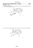
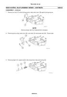
8. Install governor relay valve cover (28) over projecting stem of plunger (31). Align cover so that threaded lug is up.
Compress cover against spring pressure and install four bolts (27). Torque evenly to 9 to 11 lb--ft (12.2 to 14.9
N
S
m)
28
27
31
Back to Top


