TM-9-2520-215-34 - Page 130 of 508
TM 9--2520--215--34
0029 00--2
MAIN CONTROL VALVE ASSEMBLY REPAIR – CONTINUED
0029 00
DISASSEMBLY – Continued
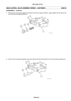
2. Remove range selector lever (9), selector lever detent assembly (10) and detent spring (11). Remove six cap
screws (12) and six lockwashers (13), selector valve cover (14) and gasket (15). Discard lockwashers and
gasket.
12
13
14
15
9
10
11
3. Remove range selector valve assembly (16) from control valve body assembly (4). Do not remove ball which is
staked into end of valve assembly.
4
16
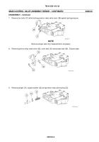
4. Remove shift inhibitor valve (17), snap ring (18), plunger (19), spring (20) and lockup timer valve (21) from control
valve body assembly (4). Discard snap ring.
20
19
18
17
4
21
Back to Top


