TM-9-2520-215-34 - Page 129 of 508
TM 9--2520--215--34
0029 00--1
MAIN CONTROL VALVE ASSEMBLY REPAIR
0029 00
THIS WORK PACKAGE COVERS:
Disassembly, Cleaning, Inspection, Fit and Wear Limits, Assembly
INITIAL SETUP:
Tools and Special Tools
General mechanic’s tool kit (item 1, WP 0088 00)
Torque wrench (item 22, WP 0088 00)
Materials/Parts
Retaining ring (item 56, WP 0087 00)
Retaining ring (item 91, WP 0087 00)
Gasket (item 63, WP 0087 00)
Gasket (item 57, WP 0087 00)
Gasket (item 62, WP 0087 00)
Gasket (item 46, WP 0087 00)
Preformed packing (item 96, WP 0087 00)
Lockwasher (6) (item 97, WP 0087 00)
Self--locking bolt (5) (item 104, WP 0087 00)
Equipment Conditions
Main control valve assembly removed
(WP 0028 00)
DISASSEMBLY
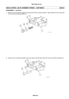
1. Remove five self--locking bolts (1), cover (2), and gasket (3) from control valve body assembly (4). Remove
external snap ring (5), shift position indicator (6), thrust washer (7), and gasket (8) from range selector lever (9).
Discard snap ring, gaskets and self--locking bolts.
1
4
2
3
6
7
8
5
9
Back to Top


