TM-9-2520-215-34 - Page 139 of 508
TM 9--2520--215--34
MAIN CONTROL VALVE ASSEMBLY REPAIR – CONTINUED
0029 00
ASSEMBLY – Continued
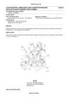
15. Install seal ring (8), thrust washer (7), shift position indicator (6) and new snap ring (5).
6
7
8
5
16. Install cover (2) and new gasket (3) on control valve body assembly (4). Install five new self locking--bolts (1).
Torque self--locking bolts to 17 to 20 lb--ft (23.1 to 27.1 N
S
m).
1
4
2
3
NOTE
FOLLOW--ON MAINTENANCE:
Install main control assembly
(WP 0028 00)
END OF WORK PACKAGE
0029 00--11/12 blank
Back to Top


