TM-9-2520-234-35 - Page 110 of 323
*C2
*C2
CHAP
5,
SEC
I I
DISASSEMBL Y
PAR
74,
STEPS
1- 4
74. DISASSEMBLY STEPS
-
INPUT TRANSFER ASSEMBLY
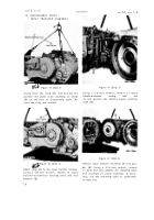
Figure 39 (Step 1)
Using hoist (A), sling (B), and bracket (C),
position the power train assembly on blocks
(D) on the floor or disassembly table, Re-
move the sling and bracket.
Figure 40 (Step 2)
Remove input transfer assembly (A) and gas-
Attach sling (A) to the input transfer housing.
Using a 5/8-inch wrench, remove 16 inpu t
transfer-to-converter housing bolts and lock
washers (B).
7 8
Figure 41 (Step 3)
Using a 5/8-inch wrench, remove 10 inpu t
transfer-to-converter
housing
bolts
and
10 lock washers (A). Remove engine coupling
shaft (B).
Figure 42 (Step 4)
ket (B). Using a 9/16-inch wrench, remove
11 bolts and lock washers (C) retaining input
and scavenge oil pump assembly. If neces-
sary, use two mounting bolts as jackscrews,
in holes (D).
Back to Top


