TM-9-2520-234-35 - Page 116 of 323
CHAP
5.
SEC
I I
DISASSEMBLY
75.
Figure 63 (Step 25)
Remove idler cluster gear and bearing as-
sembly (A).
PAR
74-7 5
DISASSEMBLY STEPS –
MAIN TRANSMISSION ASSEMBLY
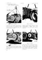
Figure 65 (Step 1)
Using a l/2-inch wrench, remove 18 bolts (A)
and flat washers (B) retaining regulator and
lockup shift control valve body assembly (C).
Figure 64 (Step 26)
Remove input oil pump drive gear (A) from
housing (B).
8 4
Figure 66 (Step 2)
Remove regulator and lockup shift contro l
valve body assembly (A) and gasket (B).
Back to Top


