TM-9-2520-234-35 - Page 120 of 323
CHAP
5,
SEC
I I
DISASSEMBL Y
PAR
75,
STEPS
15-1 8
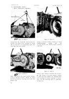
Figure 79 (Step 15)
Remove transmission top cover plate (A). Re-
move four self-locking bolts (B), baffle (C)
and gasket (D).
Figure 81 (Step 17 )
Using wrench (A), apply the transmission left
brake.
Figure 80 (Step 16)
Using a 9/16-inch wrench, remove three bolts
(A) and lock washers retaining oil screen as-
sembly (B). Using two bolts (A) as jacks crews,
loosen and remove screen assembly (B).
Figure 82 (Step 18)
Using a 1-inch wrench, and with the left brake
applied,remove the left-output shaft self -
locking bolt (A). Remove lock plate (B) and
coupling (C).
8 8
Back to Top


