TM-9-2520-234-35 - Page 112 of 323
CHAP
5,
SEC
I I
DISASSEMBL Y
PAR
74,
STEPS
9-1 2
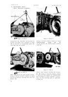
Figure 47 (Step 9)
Using a soft hammer, and while raising trans-
fer housing (A), tap lightly on the torque con-
verter assembly (B) t o remove it from the
housing.
Figure 48 (Step 10)
Using a l/2-inch wrench, loosen 24 torque
converter cover-to-pump assembly nuts (A),
and remove all but two, 180 degrees apart.
8 0
Figure 49 (Step 11)
Turn the converter over and remove the two
remaining nuts. Using three 3/8-24 bolts (A)
as jacks crews, separate lockup clutch reaction
plate (B) from cover (C). Using sling (D) and
hooks (E), remove pump assembly (F).
Figure 50 (Step 12)
Remove torque converter stator assembly (A).
Back to Top


