TM-9-2520-254-34 - Page 115 of 126
S/1
ijl
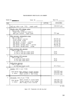
‘1’bird Iockop to third converter (At closed throttle, this
downshift slIookf occor at 1,200 to 1,300 rpm. 1
Third converter to second Iockop
%wond lockup to secomf converter
Swood converter to first lockup
First lockup to first converter
(At closed throttle a downshift from third converter
to first converter occurs at 600 to 800 rpm engine
speed.)
NOTE
To convert engine speed readings, for the
M113A1 family of vehicles, to trans-
mission
input speed,
multiply engine
speed by 1.286.
e. Lockup Shift Points.
During full-throttle
operation "at detent, ”
the lockup clutch should
engage when front governor (G1) pressure reaches
44 psi.
NOTE
All tests in
d
and e above are based on
proper adjustment of the throttle valve
(TV) linkage.
f. Inhibitor Functional Check, 3-2 Downshift.
(1) Disconnect transmission
output from
vehicle. drive line.
(2) Disconnect throttle valve linkage, and
rotate throttle valve lever on transmission coun-
terclockwise until it reaches its internal stop.
(3) Place manual selector control in 1-3
position, and accelerate engine to 2,000 rpm.
(4) Shift to 1-2 position, and slowly decrease
engine speed. The 3-2 automatic downshift should
occur at 1,560 to 1,830 rpm engine speed.
(5) If the 3-2 automatic downshift occurs at a
speed higher than 1,830 rpm, it is an indication
that the high-to-intermediate inhibitor valve is
sticking in its bore and not opening. If the
downshift speed point is lower than 1,560 rpm, it is
an indication that the valve is either sticking in its
bore in an open position or that the inhibitor valve
spring is faulty.
g.
Inhibitor Functional Check, 2-1 Downshift.
(1) Perform steps (1) and (2) as directed in
f
above.
(2) place manual selector control in the 1-2
position, and accelerate engine to 2,000 rpm.
(3) Shift to l-position, and slowly decrease
engine speed. The 2-1 automatic downshift should
occur at 1,560 to 1,790 rpm engine speed.
(4) If the 2-1 automatic downshift occurs at a
epeed higher than 1,790 rpm, it is an indication
that the intermediate-to-low inhibitor valve is
sticking in its bore and not opening. If the
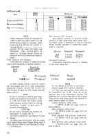
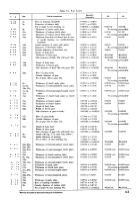
Engine speed at
full
throttle
At drtm[
Through decent
1 .
.ioo”
to 1,700 rpm
1,700 to 1,800 rpm
1.000 to 2.000 rpm
1,950 to 2,150 rpm
1,.300 to 1,700”
rpm
1,700 to 1,800 rpm
1,900” to 2.()()() rpm
l,9Fr Oto2,100rpnl
1,500 to 1 ,?00 rpm
1,700 to 1,800 rpm
downshift speed point is lower than 1,560 rpm, it is
an indication that the valve is either sticking in its
bore in an open position or that the inhibitor valve
spring is faulty.
NOTE
To convert engine speed readings, for the
M113A1 family of vehicles, to trans-
mission
input
speed, multiply engine
speed by 1.286.
5-63. Adjustments
a. Manual Selector Linkage.
Proper adjustment
of the manual selector linkage is important for
proper vehicle performance. Refer to end item
organizational manual for procedures.
b. Throttle Linkage
Underscored.
There are
two adjustments which must be made for throttle
linkage. One is internal and must be made before
the oil pan is installed. The other is external and is
made after instilling the transmission in the
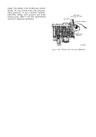
vehicle. The internal adjustment concerns ad-
justment and locking of the headless screw in the
throttle valve retainer at the rear of control valve
assembly (fig. 5-146).
NOTE
This adjustment is necessary only when a
replacement control valve assembly (3, fig.
5-82) or valve body (42, fig. 5-82) is in-
stalled. The adjustment, if required, is
made as follows:
(1) On original control valve assembly,
measure distance between rear of throttle valve
(depressed until it bottoms) and front of throttle
valve stop screw. Record this dimension (fig. 5-
146).
(2) On new control valve assembly, adjust
stop screw until distance between rear of depressed
throttle valve and front of stop screw corresponds
exactly with measurement made in (1) above.
(3) Lock stop screw by crimping threaded
portion of retainer against flat side of stop screw
(fig. 5-146).
(4) The external adjustment concerns the
linkage connecting the accelerator pedal, engine
fuel control, and transmission throttle
adjustment is extremely important
matches the transmission function to
lever. This
because it
the engine
5-65
Back to Top

