TM-9-2520-254-34 - Page 109 of 126
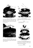
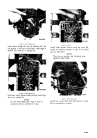
Figure 5-139
Figure 5-140
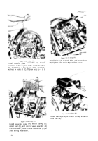
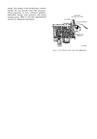
Install spacer(s) (A) and retainer (B) on each of six
drive studs (C), after removing lifting eye 4910-
573-3801 (10865773) (D) and strap 4910-572-
8608 (8356175) (E).
NOTE
Spacers selected to meet the 1.566
dimension, plus retainer thickness of
approximately 0.016 inch, will meet the
1.582 dimension in figure 5-137.
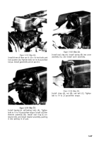
Using a hoist in sling 4910-572-8614 (8356184),
(A) remove transmission (B) from stand 4910-499-
4196 after four
5
/
8
-11 bolts are removed.
Section XIV. TESTS AND ADJUSTMENTS
5-59. General
a.
The tests in this section will determine if the
functional operation of the transmission is
satisfactory. The tests may be made after overhaul
(rebuild) or to determine the condition of the
transmission at any time. The tests may be made
while the assembly is installed in the vehicle or on a
properly equipped test stand.
b.
These tests will determine whether or not the
clutches,
gearing,
and hydraulic
system
are
performing properly.
C
.
Adjustments of the transmission assembly
components and control linkages must be correct
when tests are performed. When tests are made in
the vehicle, the engine must be properly tuned and
performing efficiently. Refer to the engine technical
manual for engine tests and adjustments. Refer to
paragraphs 5-62 and 5-63 for transmission tests
and adjustments.
5-60. Test Equipment
a. ‘Transmission Installed in Vehicle.
Th e
following equipment is required when testing the
transmission assembly in the vehicle.
(1) Tachometer to indicate transmission input
speed.
NOTE
To convert engine speed readings,
M113A1 family of vehicles, to
mission
input speed, multiply
speed by 1.286.
for the
trans-
engine
(2) Gages for reading oil pressures. Refer to
table 3-1 for pressure gage kit 4910-572-8612.
(3) Tachometer to indicate transmission
output speed (drive line disconnected at output).
(4) A bulb-type temperature indicator which
will read to 400°F., with fittings to install bulb into
oil line carrying oil to cooler.
(5) A spring to hold engine throttle linkage in
closed position while accelerator linkage is
disconnected from engine.
b. Transmission Installed on Test Stand.
Th e
following equipment is required for testing the
transmission on a test stand.
(1) The equipment listed in
a
(1) through (4)
above is required for testing the transmission out of
the vehicle. In addition, a test stand and other
equipment is needed.
5-59
Back to Top


