TM-9-2520-254-34 - Page 100 of 126
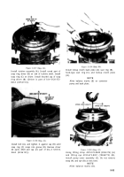
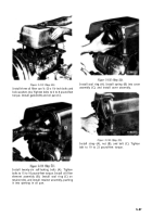
Figure 5-107.
Figure 5-108
NOTE
In step 25 (fig. 5-108), measurements for
selection of proper diaphragm gaskets are
being made. Figure 5-107 illustrates points
at which measurements are made. The
diaphragm, when install, must compress
the entire clutch pack. The selection of
proper
gaskets depends upon the
measurements taken in step 25 (fig. 5-
108). To determine gasket pack to be
installed in step 28 (fig. 5-111), average the
two measurements obtained in step 25 (fig.
5-108). Then choose gaskets as follows:
(1) If average measurement is 0.010 to
0.015-use one 6774406 (73342) (0.012 thk)
gasket
(2) If average measurement is 0.016 to
0.021—use one 6774407 (73342) (0.016 thk)
gasket
(3) If average
measurement is 0.022 to
0.027—use one 6774408 (73342) (0.021 thk)
gasket
(4) If average
measurement is 0.028 to
0.033—use one each 6774406 (73342) (0.012 thk)
and 6774407 (73342) (0.016 thk) gasket
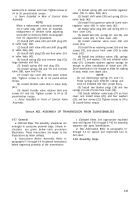
Install diaphragm (A) over guide bolts (B). Tap
diaphragm until it seats against spacers. Install six
5/16-18 x 1-inch bolts and washers (C), evenly
spaced. Tighten all six bolts to 10 pound-inches
torque. Using a thickness gage, measure clearance
between diaphragm (A) and housing (E) and (F)
and opposite side as shown. See figure 5-107.
Record both dimensions. Retighten two bolts 4910-
572-8701 (8356186) (D), and remove nine bolts
and washers (C). The average of the two dimen-
sions will be the required gasket thickness. (Guide
bolts are part of set 4910-572-8710 (8356165).)
5-50
Back to Top


