TM-9-2520-254-34 - Page 98 of 126
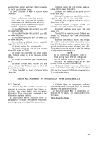
Figure 5-99
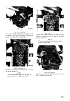
Figure 5-101
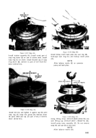
Figure 5-100
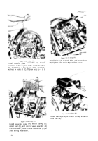
Figure 5-102
Turn assembly over, and position output shaft
through hole in table. Install low-range apply plate
(A), and alternately install three internal-splined
(B) and three external-tanged plates (C). Install
intermediate-range planetary carrier (D) and snap
ring (E).
Install two external-tanged plates (A) and two
intern al-splined plates (B). Install intermediate-
range reaction plate assembly (C) with notch (D)
alined with notch (E).
Install intermediate-range piston housing assembly
(A), apply plate (B), one internal-splined plate (C),
and
intermediate-range
ring gear (D). Note
alinement of clutch apply oil hole (E) with anchor
pin slot (F).
Install compressor assembly 4910-572-8643
(8356187) (A), to compress low-range (B) and
intermediate-range
clutch springs (C). When
properly assembled and compressed, there will be
no clearance (opening) at points (D) and (E).
5-48
Back to Top


