TM-9-2520-254-34 - Page 99 of 126
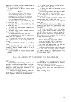
Figure 5-103
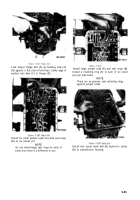
Figure 5-105
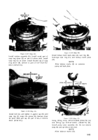
Figure 5-104
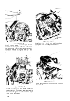
Figure 5-106
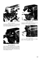
Note position of top of clutch pack relative to
transmission housing when seated. Install two bolts
4910-572-8701 (8356186) (A) to lock clutch pack
in compressed position. Tighten bolts to 10 to o12
pound-feet torque. Remove compressor assembly
4910-572-8643 (8356187) (B).
Install reverse-, intermediate-, and low-range clutch
pack (A) into housing (B) with slots (C) toward
bottom of housing.
NOTE
When properly installed, front (upper)
surface (D) of intermediate clutch reaction
plate should aline with rear surfaces of
power takeoff openings.
Install two clutch anchor pins (A). Flats on pins
must seat in slots in clutch pack.
Install two spacers (A). Using lifting eye 4910-673-
3801 (10865773), (B) install turbine shaft (C) and
high-range clutch assembly (D) as rebuilt in
paragraphs 5-17 through 5-21.
5-49
Back to Top


