TM-9-2520-254-34 - Page 92 of 126
Section XII. OVERHAUL (REBUILD) OF MAIN CONTROL VALVE ASSEMBLY
5-52. Description
Refer to paragraph 2-11 for description of the main
control valve assembly.
5-53. Disassembly
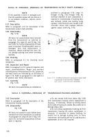
(fig. 5-82)
NOTE
All items not covered in a through c below
were removed from the transmission as
outlined in paragraph 5-6, steps 4 through
13 (fig.
5-4 through 5-13). No further
disassembly of those parts is required.
a. Items Removed from Bottom of Control Valve
Assembly.
CAUTION
Valve retainer (6) is spring loaded and
must be held compressed while removing
screws.
(1) Place main control valve assembly (3) on a
table with top side down. Remove two screws (4)
and lockwashers (5) from retainer (6), and remove
retainer, spring (7), and valve (8).
(2) Remove six screws (9).
(3) Remove bottom cover (10), detent spring
(11), and ball (12).
b. Items Removed from Front of Control Valve
Assembly.
(1) Remove two screws (13).
CAUTION
Inhibitor valve body (21) is spring loaded
and must
be held compressed while
removing screws.
(2) Remove screw (20), four screws (22), and
washers (23) and remove inhibitor valve body (21).
(3) Drive two dowel pins (19) from valve body
(21), and remove two washers (16), two springs
(15 and 17), and two inhibitor valves (18) from
valve body.
(4) Remove two springs (14 and 27) and two
blocker plugs (28) from front cover (34).
CAUTION
Front cover 34 is spring loaded and must
be held compressed while removing screws
(24 and 25).
(5) Remove three screws (24).
(6) Remove front cover (34) but do not
remove setscrew (33) from cover.
(7) Remove plug (35) from cover (34).
(8) Remove spring (36) and shift valve (38)
from control valve body (42 ).
(9) Remove spring (37), main regulator valve
(40), and front governor valve (41) from valve
body (42).
(10) Remove throttle regulator
spring (43) from valve body (42).
5-42
valve (39) and
(11) Remove screw (25), cover (26), extender
valve (29), springs (30 and 31), and ball (32).
c. Items Removed from Rear of Control Valve
Assembly.
(1) Remove screws (61 and 63), and remove
throttle valve retainer (64). Do not remove ad-
justing screw (62) from retainer.
(2) Remove throttle valve (44) from control
valve body (42).
Caution:
Rear cover (60) is spring
loaded and must be held compressed while
removing screws.
(3) Remove seven screws (59) from rear cover
(60), and remove cover.
(4) Remove trimmer valve (58), springs (56
and 57), plug (55), spring (54), trimmer stop (53),
and spring (52).
(5) Remove manual selector valve (45).
(6) Remove shift plug (47) and shift valve
(46) from valve body (42).
(7) Remove shift plug (48) and shift valve
(49) from valve body (42).
(8) Remove shift plug (50) and flow valve
(51) from valve body (42).
5-54. Cleaning
Refer to paragraph 5-2 for cleaning recom-
mendations.
5-55. Inspection and Repair
Refer to paragraph 5-3 for general inspection and
repair recommendations. Refer to paragraph 6-3
and table 6-3 for general wear limits information.
5-56. Assembly
(Fig. 5-82)
NOTE
All items not covered in
a
through
c
below
are installed as outlined in paragraph 5-58,
steps 43 through 53 (fig. 5-126 through 5-
136). No overhaul (rebuild) of such
components is required or recommended.
NOTE
It is absolutely essential that springs are
not interchanged. Refer to table 6-2.
a. Items Installed at Bottom of Control Valve
Assembly.
(1) Place main control valve assembly (3) on
a table with top side down. Install manual selector
valve (45) into valve body (42).
(2) Install detent ball (12) and spring (11) in
valve assembly, and install bottom cover (10).
(3) Install six screws (9). Tighten screws to 24
to 36 pound-inches torque.
(4) Install spring (7) and regulator valve (8)
on retainer (6). Install two screws (4) and lock-
Back to Top


