TM-9-2520-254-34 - Page 105 of 126
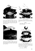
Figure 5-125
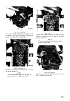
Figure 5-126
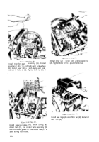
Figure 5-128
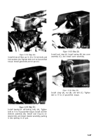
Figure 5-127
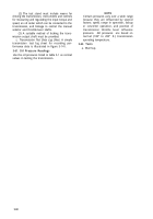
Lock output flange bolt (A) by bending lock tab
(B) against a flat side of bolt head. Stake edge of
washer into hole (C) in flange (D).
Install six small jumper tubes (A) with seal rings
(B) at six places (C).
NOTE
Do not interchange seal rings on ends of
tubes since there is a difference in size.
Install large jumper tube (A) and seal rings (B).
Install a retaining ring (C) in each of six small
jum per tube holes.
NOTE
There are no grooves; seat retaining rings
against jumper tubes.
Install rear pump check ball (A) (nylon) in cavity
(B) in transmission housing.
5-55
Back to Top


