TM-9-2520-270-34 - Page 856 of 933
TM 9-2620-270-34
REPLACE SECOND RANGE RELAY VALVE ASSEMBLY
This task covers: Remove (page 4-514). Install (page 4-517).
INITIAL SETU P
Tools:
Crowfoot attachment – (Item 20, App C)
General mechanic’s tool kit:
automotive — (Item 33, App C)
Socket wrench adapter — (Item 75, App C)
Socket wrench attachment —
(Item 82, App C)
Socket wrench set — (Item 89, App C)
Torque wrench — (Item 99, App C)
Torque wrench – (Item 100, App C)
Wire-twister pliers — (Item 107, App C)
1.
2.
3.
4.
REMOVE CONTROLLER ASSEMBLY.
See task REPLACE CONTROLLER
ASSEMBLY, page 3-32.
REMOVE LEFT-HAND OUTPUT
HOUSING. See task REPLACE
LEFT-HAND OUTPUT HOUSING,
page 4-314.
REMOVE LEFT-HAND INTERMEDIATE
HOUSING ASSEMBLY. See task REPLACE
LEFT-HAND INTERMEDIATE HOUSING
ASSEMBLY, page 4-220.
REMOVE POSITIVE CLUTCH. See task
REPLACE POSITIVE CLUTCH,
page 4-356.
DELETED.
Materials/Parts:
Lockwire–(Item 5, App B)
Transmission oil–(Item 12, App B)
Preformed packing (4)
Preformed packing
Personnel Required:
Track Veh Rep 63H10
Equipment Conditions:
Transmission mounted on tip-over stand.
See page 2-144.
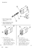
6. REMOVE DIPSTICK (1) AND
DIPSTICK TUBE ASSEMBLY (2).
a.
b.
c.
Using wire-twister pliers, remove and
discard Iockwire (3).
Using 3/8-inch drive ratchet handle and
7/16-inch socket, remove screw (4).
Remove dipstick (1) and dipstick
tube assembly (2) with clamp (5).
4-514
Change 3
5.
Back to Top


