TM-9-2520-272-40 - Page 263 of 620
TM 9-2520-272-40
0033
NOTE
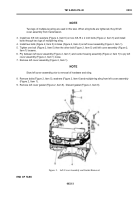
Two legs of multiple-leg sling are used in this task. When sling bolts are tightened, they lift left
cover assembly from transmission.
3. Install two 3/8 inch washers (Figure 2, Item 6) on two 3/8-16 x 2 inch bolts (Figure 2, Item 5) and install
bolts through two lugs of multiple-leg sling.
4. Install two bolts (Figure 2, Item 5) in holes (Figure 2, Item 4) on left cover assembly (Figure 2, Item 1).
5. Tighten one bolt (Figure 2, Item 5) then the other bolt (Figure 2, Item 5) until left cover assembly (Figure 2,
Item 1) loosens.
6. Pry between left cover assembly (Figure 2, Item 1) and center housing assembly (Figure 2, Item 7) to pry left
cover assembly (Figure 2, Item 1) loose.
7. Remove left cover assembly (Figure 2, Item 1).
NOTE
Stow left cover assembly prior to removal of hardware and sling.
8. Remove bolts (Figure 2, Item 5), washers (Figure 2, Item 6) and multiple-leg sling from left cover assembly
(Figure 2, Item 1).
9. Remove left cover gasket (Figure 2, Item 8). Discard gasket (Figure 2, Item 8).
Back to Top


