TM-9-2520-272-40 - Page 264 of 620
TM 9-2520-272-40
0033
INSTALL LEFT COVER ASSEMBLY
NOTE
Transmission is on maintenance stand, left end turned up.
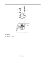
1. Install two 3/8-16 x 4 inch guide pins (Figure 3, Item 9) into center housing assembly (Figure 3, Item 7).
2. Install new left cover gasket (Figure 4, Item 8) on center housing assembly (Figure 4, Item 7), over guide
pins (Figure 3, Item 9).
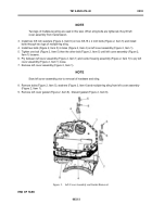
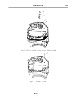
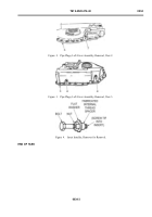
3. Install 3/8 inch f at washer (Figure 4, Item 9) on each of two 3/8-16 x 2 inch bolts (Figure 4, Item 8) and
install bolts through two lugs of multiple-leg sling.
NOTE
Bolts should not extend beyond the inside surface of left cover. If tips of bolts extend beyond
surface of end cover, then the cover will not seat on gasket.
4. Install two bolts (Figure 4, Item 5) in two holes (Figure 4, Item 4) in the left cover assembly (Figure 4, Item 1).
Back to Top


