TM-9-2815-202-34 - Page 178 of 670
TM 9-2815-202-34
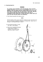
4-22. FLYWHEEL ASSEMBLY REPLACEMENT (Cont)
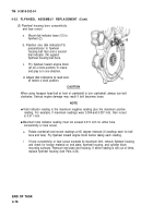
(2) Flywheel housing bore concentricity
and face runout
a.
Mount dial indicator base (12) to
flywheel (2).
b. Position one dial indicator(13)
perpendicular to flywheel
housing bell face and a second
dial indicator (14) against
flywheel housing bell bore.
c.
Pry flywheel toward engine block
(at six o’clock position) to insure
end play is in one direction.
d. Adjust dial indicators to read zero
at twelve o’clock position.
CAUTION
When using hexagon head bolt at front of crankshaft to turn crankshaft, always
clockwise. Serious engine damage may result if bolt becomes loose.
NOTE
●
Total indicator reading is the maximum negative reading plus the maximum
turn bolt
positive
reading. For example, if maximum readings were 0.004-and-0.007 inch, then runout
is 0.011 inch.
●
Maximum total indicator reading must not exceed 0.013 inch for either bore
concentricity or face runout.
e. Rotate crankshaft and record readings at 60 degree intervals (6 readings each for bell
bore and face). Pry flywheel toward engine block before taking each reading.
f.
If bore concentricity or face runout exceeds its maximum limit, remove flywheel housing
and check for foreign material on end plate, flywheel housing, and cylinder block
mounting surfaces. Remount end plate and housing. If either reading is still out of limits,
replace flywheel housing (see Para 4-24).
END OF TASK
4-76
Back to Top


