TM-9-2815-202-34 - Page 187 of 670
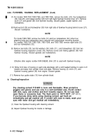
TABLE 4-1
TM 9-2815-202-34
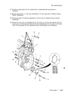
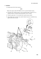
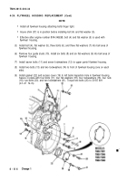
(10) Install bolt (29) and Iockwasher (30) to right side of flywheel housing.
When tightening idler gear hub bolts, turn engine crankshaft to prevent any bind of idler
gear bearing. Also rotate crankshaft when tightening flywheel housing bell bolts.
(11 ) Tighten flywheel housing attaching bolts to specifications shown in Table 4-1 (Operation 1).
Draw mating parts together evenly. See Operation 1 figure for initial bolt tightening
sequence.
(12) Torque all flywheel housing attaching bolts to specifications shown in Table 4-1
(Operation 2). Refer to Operation 2 figure for final bolt tightening sequence.
Three 3/8-24x4 1/2 inch bolts and one 3/8-24x4 3/4 inch bolt required for model 7083-7398.
OPERATION 1
OPERATION 2
4-85
Back to Top


