TM-9-2815-202-34 - Page 587 of 670
TM9-2815-202-34
NOTE
c.
d,
e.
f,
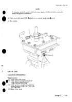
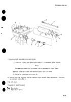
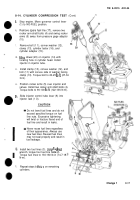
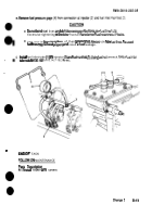
Bar engine over to bring upper ends
of push rods of injector and valve
rocker arms in line horizontally.
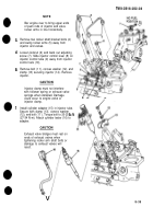
Remove two rocker shaft bracket bolts (4)
and swing rocker arms (5) away from
injector and valves.
Loosen locknut (6) and back out adjusting
screw (7). Slide injector control lever (8) on
injector control tube (9) away from injector
control rack (10),
Remove bolt (1 1), convex washer (12), and
clamp (13) securing injector (14). Remove
injector.
CAUTION
Injector clamp must not interfere
with follower spring or exhaust valve
springs when installed. Damage
could occur to engine valve or
injector clamp.
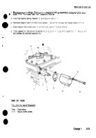
Install cylinder adapter (15) in injector tube.
Secure with clamp (13), convex washer
(12), and bolt (11 ). Torque bolt to 20-25 Ib-ft
(27-34 N-m). Attach cylinder tester (16) to
adapter.
CAUTION
Exhaust valve bridges must rest on
ends of exhaust valves when
tightening rocker arm shaft bolts or
damage to exhaust valves will
result.
n
v
8-35
Back to Top

