TM-9-2815-205-24 - Page 180 of 856
INSTALLATION - Continued
9.
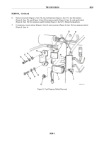
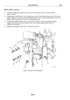
If removed, install elbow (Figure 4, Item 5) and connector (Figure 4, Item 15) in pressure switch
(Figure 4, Item 4).
10.
Install pressure switch (Figure 4, Item 4), pad (Figure 4, Item 20), pad bracket (Figure 4, Item 19), two flat
washers (Figure 4, Item 18), two new lockwashers (Figure 4, Item 17), and two bolts (Figure 4, Item 16) on
pressure switch bracket (Figure 4, Item 21). Loosely tighten bolts.
11.
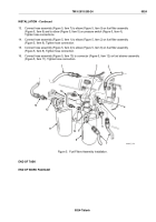
Connect tube assembly (Figure 5, Item 14) to connector (Figure 5, Item 10) on fuel filter assembly
(Figure 5, Item 8) and to connector (Figure 5, Item 15) on pressure switch (Figure 5, Item 4).
Tighten tube connections.
12.
Torque two bolts (Figure 4, Item 16) to 13–17 lb-ft (18–23 N·m).
16
17
18
19
20
21
5
4
15
16
17
18
MAINT_073
Figure 4.
Pressure Switch Installation.
TM 9-2815-205-24
0024
0024-6
Back to Top

