TM-9-2815-220-24 - Page 728 of 1563
TM 9-2815-220-24
OIL COOLER ACCESS COVERS AND FRAMES REPLACE/REPAIR
0090 00
REMOVAL/INSTALLATION (Continued)
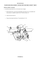
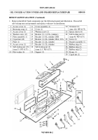
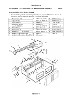
1. Remove/install left bank components per the following legend and illustration.
Discard all
self-locking nuts and grommets and replace with new on installation.
1 Access cover (1)
11
Cover assembly (1)
20
Grommet (6)
2 Retaining strap (1)
12
Cover (1)
(item 100, WP 0175)
3 Access cover (1)
13
Washer screw (2)
21
Spacer sleeve (6)
4 Washer screw (17)
14
Bracket (3) (1,2,5L cylinders)
22
Self-locking nut (6)
5 Plate assembly (1)
14
Bracket (1) (6L cylinder) 2DR
(item 40, WP 0175)
6 Caged nut (40)
15
Bracket (1) (6L cylinder) 2DA, 2CA
23
Screw (6)
7 Plate (1)
16
Bracket (1) (4L cylinder)
24
Bracket assembly (1)
8 Access cover (1)
17
Bracket (1) (3L cylinder)
25
Rubber strip (4)
9 Self-locking nut (18)
18
Self-locking nut (6)
26
Rubber strip (2)
(item 33, WP 0175)
(item 113, WP 0175)
27
Rubber strip (2)
10 Flat washer (6)
19
Support (3)
28
Frame (1)
29
Caged nut (2)
12
13
11
6
7
6
9
4
8
5
1
10
4
3
2
28
29
25
25
27
27
26
26
6
24
23
20
21
22
19
18
14
16
14
17
15
14
9
2DR
WP 0090 00-2
Back to Top

