TM-9-2815-220-34 - Page 183 of 532
of each vAlve (8). DisconneCt Two outLet hoses
(9±
From TWo fItt²Ngs on s³de o´ MoUnting brackeT
(7µ)µ
D³sconnect tWo outlet Hoses (¶± from Bottom
f·T-
t³ng on eAc¸ vA¹ve. RemovE oUtleT Hosesº
»oosen
¼ocK³ng nut (10± on eacH vAlve And sl³de vAlves
ouT
of moUn½¾ng ¿ÀAcketÁ
(3)
On ÂVDSÃ1Ķ0Å2DÆ only, ÇeMove oi¹
sAMpl·ng vAlve FÇom ÈÉoÊT of o·¹ ˳lteÇ HoUs³ng
coveÇ (f³gÌ ÍÎ7Ï3)Ð
b. JnslaL±Alion²
(
l± ÑÊstAll MoUÒt²Ng brAckÓt
in
A v³seÔ And
³nstAÕ tHe vAÖves As shown in ˳gUre ×ØÍ48ÌÙ1Ú w³t¸
the HAnÛlJes Ünd THe ³nlÝT porTs ´Þc·ng oppos³te ßAcH
othÝÇ And p àáâle¹ to ¿ottom ãlAnges äf MoUnt³ng
BråckeTæ çecure bot¸ vA¹ves ·n moUnt³ng BÇAcket ¿y
èig¸ten³ng jAM nUt W¸·¹e Hold¾ng a wrenéH on nut
dêrectly belë·nd ¿rAcìet WAl¹Ï
(×)
íonneît
ouTlet
¸oseï
to
vAlvðs
(figÌ
×ñÍ48ÏÍͱò íonnÝct opposóte eÊds oô tWõ ouö¹eT
hoses to ÷·èt³ngs on øoUnt³ng ¿rAcùeT s·de flAngeÏ
(3) ÂttAc¸ engine o·ú ³ÊûÝt l·ne (fügý ×þâ48ÿÍÍ)
to lefT vAlveÏ ÂttAch trAnsm³Ās³on o·l ·nlet lāne to
r³gHt vAlveÌ
(4) RÝmove o·¹ sAmpl³ng vAlve AssÝm¿ly FÉoM
Ă³se And secure to rigHt reAr upper cover witH two
AssăĄBlEd wAą¸ÓĆć ¿o¹ts (6Ĉ ĉ·gĊ ×ñ14ċČÍč)Ď
(5± ÂtTAch trAnsnďss·on o³û ·ĐđeT l·ne (3) to
AdApter (4±Ï ÂttAĒH enGne oiē ³nēet Ĕ³ne (×) to tEe
(Í ±Ð çăcUre botH ünĔeT l·neĕ to rigHt upper covers
WitH FoUr AsseMb¹ed WAsher ¿olts And ¹oop ĒJAMps
(5)Ė
TM 9-2815-220-34
(6) ėn Ęodel ÂęĚSěÍ79čÃ×DĜ onĝyĞ iğĠġtAJl
I
one o·l sAmpl·ng Toggle vAlve to o³l ´·ēTeÇ HoUs·ng
´ront cover
±fg.
Í
-
7
²3³
Ð
tA±6²7³´
I
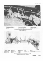
Figure 2· 148. J ±²
Removing Or I1±st²l/³´µg
oI
saMplINg VAL¶ES
I
I· br¸ck¹T
2-49²5²
Clean Air System
I
ÆeĢģr to íHapter 4 For removAl and ³nstAl¹ATion pÇĤĥ
cedurĦ
ħor
t¸e
c¹Ýan
a
systeM
on
Ĩĩodels
ÂĪDSī¹ 7¶0ñ×í And ÂVDSñĬ 7¶čñ×DÂĭ
SecTIoN V±. SERV±CE OPERA²³O´S
µ¶·¸.
GeNeµ¶L
This section covers serViCe opera±Ions alloCa±ed ±o
±he DireC± SuppoR² and General SUppor± Main±e-
nanCe Organiza±ion. ProCedUres o³±lined in ±his
seC±ion are f´r serviCe opera±ions reqUiring a
mini
mum
of
engine disassembly ±o performµ
µ¹·º»
Che·k¸¹g CYLºNdeµ Compµe»»IoN
a.
GeNer¼l½
For ins±rUC±ional pUrposes
in
±his
seC±ion alL ¶Ue· inje¸±or nozzle and holder as¹
semBlies
ĮįlÖ
ºe removed and a Compression ±es±
İılIJ
»e made on al¼ Cylinders½
WAR´¼½G
¾± is reCommended ±ha± a¿l nozzles Àe reÁ
moved when perfÂrminà a Co
mp
ress
³
on
CheCkÄ Nozzle removal
ĮįlÖ p
re
v
en± ±he
possiÅili±Y of ±he e
n
gi
n
e firing on o±her
Cylinders When ±he engine is Cranked,
ijnd
İ·ll p
er
Ą·
± ±he engÆne ±o be Cranked a± ±he
desired ÇÈÉ ±o CheCk CompressionÄ
b¾ S¿wRÀIÁg EÂgÃÂeÄ
ÊheCk ±he vehiCle Ëa±±eries ±o
assUre a
ĴU¹L
CharÃeÌ
ijnd ĵĶplķĸĹ ³Ĵ
neCessaryÍ
ÎeÏeÐ ±o ±he per±inen± opera±or's
mÅÆuÇL FÈ
enÑ
ÃÆne s±aÒÓing proCedUresÔ S±aÕÖ en×ine and allow
enÃØne ±o reaCH normal opera±ing ±empera±Ure
ijnd
±hen s±op engÆneÙ Úu± oÛf ÛÜeÝ sÞppßy so engàne
W·l¹ not del³ver Ëĺel Whiúe perFo
rnĻļ
ng
Ľ
coM
pr
ess
³
on
testº
ÉOÊË
íompress³on Test·ng Must Be perôľÉMed w³t¸Ŀ
³n An hour aFTer sTopping t¸e eng³neŀ
c³
DIs³S´emB±yµ
(Í)
Remove coo¹³ng ÷An vAnesĈ cooŁłng ËAnsĈ
eng·ne Upper coversÔ cool³ng ÷An sHroudÔ And fuel
³nŃeîtor Tĺ¿esÔ reËÝr to pArAgÉApń ×ñ× lŅº
(×) Æemove fue¹ ³ņŇector nozz¹e And ¸oldeÇ
Asïem¿¹³esň refeÇ To paÇAgÇAph ×ʼn3Ŋº
dÌ
ComprEsS;o1¶ T·st¸
(1) Pos·Tion neW ³nŋector nozzle gaskeT (Ëig.
×ñ14¶) on end oË coMpress³on AdapteÇÔ ŌarT ōoŎ
87430×ŏĎ Âppúy A liŐőt coAting of greAse on gAskeT
so ·T Œdńeres To Adapter W¸en ³nstalled ³œ cylindeÇŔ
(2± ŕnstAll adapteÇ ³nto ËUel ³nŖeŗtor nozzle
ho¹der open³ng And t·ghTen securely using cÇoW÷oot
AttAc¸mentŘ PArT řoŎ
Í
××54×44Ŏ
(3) ĝnstA¼¹ gAge Assem¿lyŘ PArt řoŚ
Î
08¶9Í80
(śg. ×ñâ5č±
on AdapterŘ PArt řoŜ 87430×ŝ
And
ChÏÐÑÒ Ó
ÔÕÖ×
Back to Top


