TM-9-2815-220-34 - Page 189 of 532
22-1/2 OEG
_
_±
I
CftHeR LIN±
+
oF crAnKShaFT
i
²
³´E
:
alµ DIM¶²sIo·¸ ¸¹oW² ºR»
I· I·Ch¼S.
½a0¾¿478
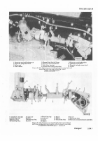
Figure f./55± Fl1wheEL tIm²ng maRk
loctiOn•.
F³gu´µ ¶·¸56¹ º»Mov³nG
o
INatAL±I²g v³±Ve T´mIµg ³CCEu ¶o·¸r¹
2-167).
Turn valve adjUsting screw and set VaLve
cLearance to
0±1²0
inch, using thIckness gage bLade
par±
.
number
10882³17±
Gage Blade mUst Move
²hroUgh cLerance with a slight drag³ Torque
tigh´n LoCK nut to
1´6
PoUnd-inches after settµng
cLearance¶ ·hecK clearance to maKe cer±aIn settIng
has no² changed¸
dµ Checking Valve TImINg
Turn f¹yWheel CoUnº
terc»ocKwise¼ vieWed FRom rear½ UntIL Pad on va¾ve
tM 9·¸¹º5»¼¼½¾34
F³gu´e T-¼57½
Setting
Iº»¼k½ 1¾¿±·½ CL½¼Rn¶¸/ ÀÁ±Â²d¸r 6ÃÄ
AdJUstµng scReW µs ¿ust fRee of the vaLve stem (inÀ
²Ake ValVe hAS JÁs² ÂloseDÃ fµgÄ
2¿1À8)Á Â
n thIs PosiÅ
²Ion the flYWhee¹ ÆAÇk
"ÃR
ÈNT ·ÉOÊE
0Ä1²0
ÅLRÆ
shoUËd Be aLµned With poµnter ÌÍgÎ
2Ç1ÈÉ)Á Âf
flYWheel ÆAÇks aRe not Alined wÏth poInter wIthin
ÊË ÌÍÎH
at
ÏHE
²IÆe
ÐHE
Ad¿Usting scReW pAd BeÐ
coÆes fRee of VÑÒVe s²emà it WILl be necessary to
TºÀÁÂÃ9Ä
FiGUR¾¿ÀÁ58Â
Cr
A
e
T
O
n QÅLIndÆr8à Çhowȵg poÉ»Êoµq
ËmÇHÌÍf
ÃObeAÄÅRVÆÇv¾ ÈÉÊËNGÂ
CHÌÍÎÏ
Ñ
ÒÓÔÕÖ3
Back to Top


