TM-9-2815-220-34 - Page 185 of 532
Figure
2-1 9. l
1±stnlLI1²N oR ³EmOvI´G
compressiOn adPter±
fIqUµ
²³150.
Ch¶cki·G cylI¸d¹r
C´MµRESSI´N
e.
Co1±±²>1·³´:.-iµ¶¸± VurIaf¹O¸º»
After all
¼2
cylinders
are CheCked, DeTermine Lhe pRessu±'e diFFereNCe be-
²weeN high aND low ³ylinder ReadiNg. ´his vaRia-
²ioN shoUµD No² ex¶eed
70
psi· 1f CompressioN read-
iNgS aRe Below ²he low limi² of
330
Psi, ²he e¸gIne
Mo²o¹ºng »¼½ sho¾ld Be CheCked ²o be sURe ²ha¿ i²
Às
½40
¿O
·8¸
Á¼Âà Äomp¹essioN sho¾ld Be CheCked
again ²o coNFiRm the pReVioÅs ReaDings BeÆÇre
sUBmittiNg an eNGiNe fǹ oveRhaUlÈ Áemove ComÉ
PressioN Gage fRom adapter. Áemove adaPTer and
gaske² (fÊg.
¾¿ÀÁ 9)Â
ËÊsCaRD gaske².
TM ÃÄÅ8Æ5ÇÅÅÈÇÉÊ
FË AssemblyÌ
ÌNs²all fUel injeC²ÍR nozzle aNd
holder assembliesÎ paragRapH
2Í4ÎBÏ
ÏNs¿aÐl fÑel
iNJeÒ²oR ²UbesÓ pa¹agRaPh
ÐÑÐÒÓÔ
ÌNsÔall oiÕ CoolersÖ
CoolÊNg faN shRo¾d× eNgiNe ¾pØeR CoveRs× CooliNg
fans and Cooling fan vaNesÓ RefeR ²o paRagRÙph
2Õ27Ö
and paRagraph
×ØÙÒÓÚ
ÛÜÝÞß
Adjusting InTake and ExhaUS± Valve
CLearaNce
àá DâSãSSEäÓLYå
(æç
Áemove CooÚiNg fÙN vaNesÛ cooliNÜ FÙÝsÓ
eNÞne upPe¹ Cove¹sÓ CÇoling fÙN shßàáÑD anD fUel
inâec²o¹ ²UBesã ÁefeR äo paRÙgRapå
2-±lu.
è2é
»emove oæl Coole¹s. ÁefEr to paRagRÙph
2ê27ëì
èíî
ÁeMove ¿Wo selfçloCkÊNg bol²s
ïÀ,
FèÜé
ðñÀòÀó
sÑppor²
ô¾õö
aNd aCCess CoêeR
÷øùú
»emoëì aND dis-
CaRD gasket
ûüýþ
»emove ²wo maChine Boíts
ÿĀā
aND
²wo îa² washeRs
Ă6ă
aNd Remove aCCess CoïeR
\7Ąą
Áemoëe and disCard gaske²
ĆćĈĉ
NĊtċ
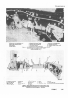
All of the ëalve adJUs²ing scReW acc sð
Coëe¹s aRe RemoveD or iNs²alñed iN the
same manNeRò
¹
SeLf²³ocking bO´t
º »u¼¼O½T
3
ACCess µ¶ver
4
Ga·kET
¾
M¸¹hINe BoLº
6
Fl»¼ w½¾HER
7
A¿CesÀ ÁOVeÂ
¿
ÃľKeÅ
ºIGu³»
À³1Á1Â
¼¹M½T¾I¿ÀG
´Ã
ÁÂaÃAÄÅIÆÇ
vALVÄ
ÈDjÉSÃiÂG ÊË̹w ÈccÍÎÎ
C´ÅEÆÇ
nČTč
óefo¹e CheCking or adJus²ông eXhaUs²
aNd/or in²ake valve õlearaNCeÓ maKe sö¹e
Bo²h valves a÷e Cøosed oN ²ùe CYlinder
BeiNg CheCkedú ûURn Craükshaf¿ as shoýn
chĎďgĐ đ
ÅĒÃēĔÆ
Back to Top


