TM-9-2815-225-34-P - Page 254 of 736
TM 9-2815-225-34&P
0026 00
0026 00-2
TURBOCHARGER (Contd)
DISASSEMBLY
1.
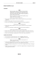
For removal of turbocharger, refer to WP 0010 00.
2.
Scribe locating mark (2) on impeller housing (1), bearing housing (4), and turbine housing (3)
before disassembly.
3.
Remove two adapters (12) and (19) from bearing housing (4).
4.
Remove two locknuts (8), screws (11), four washers (7) and (10), and V-band clamp (9) from
impeller housing (1), bearing housing (4), and turbine housing (3). Discard locknuts (8) and
screws (11).
5.
Remove impeller housing (1) from bearing housing (4).
6.
Remove turbine housing (3) from bearing housing (4).
7.
Remove impeller locknut (6) from wheel and shaft assembly (23). Discard locknut (6).
8.
Using press, remove wheel and shaft assembly (23) and turbocharger impeller (5) from bearing
housing (4).
9.
Remove heat shield (21) and insulated packing (20) from bearing housing (4). Discard insulated
packing (20).
10.
Remove diffuser plate (15), bearing insert pad (17), and bearing (18) from bearing housing (4).
Discard bearing insert pad (17), bearing (18) and diffuser plate (15) which includes sleeve (13),
ring seal (14) and O-ring (16).
11.
Remove two ring seals (22) from wheel and shaft assembly (23). Discard ring seals (22).
CLEANING AND INSPECTION
1.
For general parts cleaning information, refer to CLEANING, WP 0051 00.
2.
For general parts inspection information, refer to INSPECTION, WP 0051 00.
NOTE
Replace any part that does not pass visual inspection or is
outside specified wear limits.
3.
Inspect impeller housing (1) and turbine housing (3) for cracks, chips, and scratches. Remove
small scratches and chips from machined surfaces with crocus cloth.
4.
Inspect diffuser plate (15) for cracks or damage at bearing insert pad (17), contact point.
5.
Inspect heat shield (21) for cracks and chips.
6.
Using a straightedge, inspect heat shield (21) for straightness. Discard heat shield (21) if warped.
Back to Top


