TM-9-2815-225-34-P - Page 258 of 736
TM 9-2815-225-34&P
0026 00
0026 00-6
TURBOCHARGER (Contd)
ASSEMBLY
1.
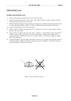
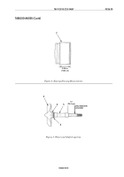
Apply OE/HDO 30 lubricating oil to new bearing (16) and install in bearing housing (17).
2.
Bend edges of new bearing insert pad (15) over bearing housing (17). Apply OE/HDO 30
lubricating oil to bearing insert pad (15) and install on bearing (16).
3.
Apply OE/HDO 30 lubricating oil to new ring seal (12) and install on new sleeve (11).
4.
Install new sleeve (11) and ring seal (12), with spiral grooves facing bearing, in new diffuser
plate (13) until sleeve is flush with turbocharger impeller (1) end.
5.
Apply OE/HDO 30 lubricating oil to new O-ring (14) and install on diffuser plate (13).
CAUTION
Do not rotate diffuser plate after assembly. Any rotation will
displace and damage bearing insert pad.
NOTE
Ensure bearing insert pad is centered during diffuser plate
installation.
6.
Install diffuser plate (13) on bearing housing (17).
7.
Position new insulated packing (19) on bearing housing (17), with flat side of insulated
packing (19) facing out.
8.
Align heat shield (20) locating tabs with depressions in bearing housing (17) and install heat
shield (20) on bearing housing (17).
NOTE
New seals must be expanded slightly before installation. Do
not overexpand seals or an improper fit on wheel and shaft
may occur.
9.
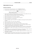
Install two new seals (21) on wheel and shaft (22). Rotate seal gaps 90º apart.
WARNING
Turbine wheel machined edges are very sharp. Wear
protective gloves when handling turbine wheel. Failure to do
so may result in injury to personnel.
10.
Install wheel and shaft (22) in bearing housing (17). Ensure heat shield (20) and sleeve (11)
remain in position.
11.
Using press, install turbocharger impeller (1) on wheel and shaft (22).
12.
Install new impeller locknut (2) on wheel and shaft (22). Tighten locknut (2) 20–24 lb-ft
(27–32 N
•
m).
13.
Apply antiseize compound to turbine housing (23). Align mark (7) made on turbine housing (23)
to mark (7) on bearing housing (17). Install turbine housing (23) on bearing housing (17).
14.
Apply antiseize compound on impeller housing (6). Align mark (7) made on impeller housing (6)
to mark (7) on bearing housing (17). Install impeller housing (6) on bearing housing (17).
15.
Install V-band clamp (5) on impeller housing (6), bearing housing (17), and turbine housing (23)
with two new screws (9), four washers (3) and (8), and two new locknuts (4). Tighten locknuts (4)
58–68 lb-in. (6.6–7.7 N
•
m).
16.
Apply antiseize compound to two adapters (10) and (18) and install on bearing housing (17).
Tighten adapter (10) 20–25 lb-ft (27–34 N
•
m). Tighten adapter (18) 50 lb-ft (68 N
•
m).
17.
Using feeler gauge, measure clearance between turbine housing (23) and V-band clamp (5).
Minimum clearance is 0.035 in. (0.889 mm). Loosen V-band clamp (5) and adjust turbine housing
(23) as necessary to obtain correct clearance.
18.
Using feeler gauge, measure clearance between impeller (1) and inside of impeller housing (6).
Minimum clearance is 0.006–0.025 in. (0.152–0.635 mm). Loosen V-band clamp (5) and adjust
impeller housing (6) as necessary to obtain correct clearance.
Back to Top

