TM-9-2815-225-34-P - Page 266 of 736
TM 9-2815-225-34&P
0027 00
0027 00-6
TURBOCHARGER HT-3B (Contd)
ASSEMBLY
CAUTION
Retaining rings must be installed with beveled edge facing
bearing. Excessive bearing wear can result if retaining rings
are installed incorrectly.
NOTE
Apply lubricating oil to all internal parts before assembly.
1.
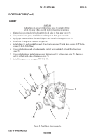
Install two new retaining rings (7), new sleeve bearing (9), and new sleeve bushing (8) in bearing
housing (11).
2.
Install heat shield (6) and new seal ring (5) in bearing housing (11).
3.
Install two new retaining rings (13) and new sleeve bearing (14) in bearing housing (11).
4.
Install two dowel pins (12), new thrust collar (15), and new thrust bearing (28) in bearing
housing (11).
5.
Position new oil baffle (27) in bearing housing (11).
6.
Install new seal ring (24) on new oil slinger (25), and install new O-ring (26) on new oil seal
plate (23).
7.
Install oil slinger (25), oil seal plate (23), and new retaining ring (22) in bearing housing (11).
8.
Install two new seal rings (4) on wheel and shaft (3).
9.
Install wheel and shaft (3) in bearing housing (11) heat shield (6) side.
10.
Install impeller (21) and new locknut (20) on wheel and shaft (3). Tighten locknut (20) 30 lb-ft
(41 N
•
m).
11.
Apply antiseize compound to threads on V-band clamp (10) and to mating surfaces of turbine
housing (1) and bearing housing (11).
12.
Position V-band clamp (10) on bearing housing (11).
CAUTION
Use care when installing turbine housing on bearing housing.
Turbine blades can be easily damaged.
13.
Align scribe mark (2) on turbine housing (1) with scribe mark (2) on bearing housing (11). Install
turbine housing (1) on bearing housing (11) with V-band clamp (10) and nut (29). Tighten nut (29)
10 lb-ft (13.6 N
•
m).
CAUTION
Use care when installing impeller housing on bearing housing.
impeller blades can be easily damaged.
14.
Align scribe mark (2) on impeller housing (18) with scribe mark (2) on bearing housing (11).
Install impeller housing (18) on bearing housing (11) with two clamping plates (19), ten new
lockwashers (17), and screws (16). Tighten screws (16) 5 lb-ft (6.8 N
•
m).
NOTE
Turbine blade-to-turbine housing measurement area shown.
Impeller blade-to-impeller housing measurement similar.
15.
Using feeler gauge, check turbine blade (30)-to-turbine housing (2) clearance. Minimum clearance
allowed is 0.008 in. (0.20 mm).
Back to Top

