TM-9-2815-225-34-P - Page 267 of 736
TM 9-2815-225-34&P
0027 00
0027 00-7/8 blank
TURBOCHARGER HT-3B (Contd)
END OF WORK PACKAGE
ASSEMBLY (Contd)
16.
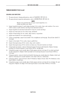
Using feeler gauge, check impeller (19)-to-impeller housing (18) clearance. Minimum clearance
allowed is 0.006 in. (0.15 mm).
17.
Using dial indicator, check wheel and shaft (3) end play. Wheel and shaft (3) end play should be
0.001–0.004 in. (0.254–0.1 mm).
18.
Remove two bolts (31), turbocharger mounting plate, and turbocharger HT-3B from ball joint vise.
19.
For turbocharger HT-3B installation, refer to WP 0046 00.
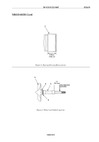
Figure 6. Turbocharger HT-3B Assembly.
Figure 7.
Turbocharger HT-3B Assembly.
4
8
9
14
17
26
24
20
3
5
6
7
7
10
27
25
23
16
12
13
15
21
19
2
22
28
13
29
2
1
11
2
18
30
2
31
3
FEELER
GAUGE
DIAL
INDICATOR
BALL JOINT VISE
MOUNTING PLATE
Back to Top

