TM-9-2815-225-34-P - Page 259 of 736
TM 9-2815-225-34&P
0026 00
0026 00-7/8 blank
TURBOCHARGER (Contd)
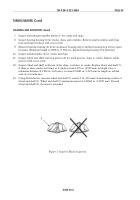
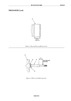
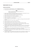
Figure 6. Turbocharger Assembly.
ASSEMBLY (Contd)
19.
Using feeler gauge, measure clearance between wheel and shaft (22) and turbine housing (23).
Minimum clearance is 0.005–0.043 in. (0.127–0.092 mm). Loosen V-band clamp (5) and turbine
housing (23) as necessary to obtain correct clearance.
20.
Using dial indicator, measure wheel and shaft (22) end play. Wheel and shaft (22) end play must
be within 0.006–0.0018 in. (0.152–0.457 mm). Loosen and retighten impeller locknut (2) until
correct endplay is obtained.
21.
For installation of turbocharger, refer to WP 0046 00.
END OF WORK PACKAGE
2
4
19
15
14
12
6
5
3
1
23
22
8
9
20
18
17
13
10
16
11
7
7
7
21
Back to Top

