TM-9-2910-226-34 - Page 28 of 208
TM 9-2910-226-34
NOTE
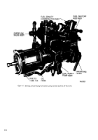
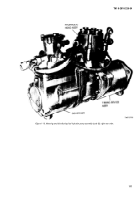
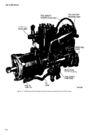
The hydraulic heads on code F and G in-
jection pumps, (fig. 1-14 and 1-15) had
additional passages that directed the flow of
lubricating oil to the lower portion of the fuel
plunger and the plunger drive gear. If these
hydraulic heads are replaced by later model
heads it will be necessary to plug the oil
passage in the injection pump housing with
parts kit 5704374.
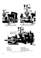
d.
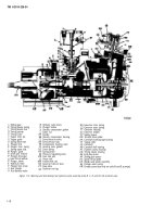
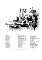
The fuel plunger is lapped and fitted into the
hydraulic head as well as in the plunger sleeve. Two
parallel flat surfaces on the lower extension of the
fuel plunger lock the plunger drive gear with the
plunger guide (M). The plunger guide is designed to
shear if the fuel plunger freezes,
e.
The drive gear thrust washer (Q) is placed
between the drive gear and hydraulic head to take
the thrust of the plunger drive gear, The spring
upper and lower seats (L and H) and plunger inner
spring (K) are held on the plunger by two plunger
locks (J), The plunger button (X) mates the round
surface of the fuel plunger end to the flat surface of
the tappet guide (G). The preceding components are
fastened to the head by the drive gear retainer (N).
This retainer is cut away to permit the meshing of
the plunger drive gear with the quill shaft gear and is
also used for fuel pump timing.
1-9. Overflow Valve Assembly.
The overflow valve
assembly (A, fig. 1-13 ) returns the excess fuel from
the hydraulic head to the vehicle fuel tank. The valve
assembly is located on the fuel outlet passage of the
hydraulic head. It consists of an overflow valve and
valve spring which maintains a constant fuel
pressure in the hydraulic head. The overflow valve
has a small opening which allows any air ac-
cumulation in fuel passages to escape. The opening
also serves as a continuous bleed of fuel to permit
cooling of the pump.
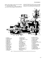
1-10. Camshaft.
NOTE
The key letters shown in parentheses refer to
figure 1-16. The camshaft (ZZ) is supported
at the front of the fuel pump housing by the
camshaft ball bearing (AB) and at the rear
by the camshaft bushing type bearing (XX).
The camshaft is comprised of a shaft with a
three-lobed cam and a spiral worm gear. The
worm gear drives the quill shaft and the fuel
supply pump.
1-11. Tappet Assembly.
NOTE
The key letters shown below in parentheses
refer to figure 1-16. The tappet assembly is
located between the camshaft and the lower
end of the fuel plunger. It consists of a
tappet roller (YY), tappet roller pin (F), and
a tappet guide (G). The tappet guide con-
tains a slot which rides on the tappet guide
pin in the injection pump housing.
1-12. Quill Shaft Assembly.
NOTE
The key letters shown below in parentheses
refer to figure 1-13. The quill shaft assembly
transmits the rotary motion of the camshaft
to the fuel plunger at one-half camshaft
speed. The quill shaft assembly consists
of a quill shaft (L), quill shaft bushing (K)
two shaft spacers (H), and a camshaft
driven gear (G). The quill shaft assembly is
held in position in the injection pump hous-
ing by a machine screw (J).
1-13. Governors (Typical).
NOTE
The key letters shown below in parentheses
refer to figures 1-16 and 1-17, except where
otherwise indicated.
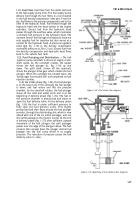
a.
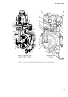
The governor,
with its weight and spider
assembly attached to the camshaft, is an integral
part of the fuel injection pump. The governor is a
variable speed, mechanical and centrifugal type. The
governing action is accomplished by two governor
weights (UU) acting against a movable sliding sleeve
(VV) which is backed up by governor inner and outer
springs (RR and SS) loaded in opposite directions.
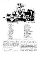
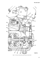
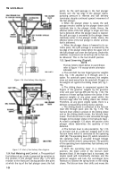
(1) The governor on code A injection pump (fig.
1-1 7) is the same except a torque control link ((D),
fig. 1-18) has been added.
(2) The control link retards governor action
during automatic transmission shift and does not
allow engine speed or torque increase during the
change of gear ratios within the transmission. This
action alleviates shift shock to the transmission.
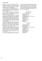
KEY to fig. 1-18
G
A
B
C
D
E
F
E
J
K
L
M
N
P
Weight and spider assembly
Oil baffle
Torque link spring
Torque link
Guide
Sliding stop wedge
Smoke limit
Stop plate
Fulcrum lever assembly
Torque link pin
Contact surface
Operating shaft
Torque link pin
Contact surface
1-20
Back to Top

