TM-9-2920-257-30-P - Page 90 of 111
TM 9-2920-257-30&P
Turn the calibrate knob to increase reading on the tachometer to value
determined by e (speed of test generator) in above formula.
Increase
or reduce test stand speed with vari-drive control until tachometer
indicates desired test speed (2,000 RPM).
In the formula below, the
3-inch pulley on the test generator will be turning 2,666 RPM when the
test stand tachometer indicates 2,000 RPM.
2000 X 4 = 8000 = 2666 RPM
3
E-3.
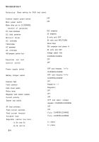
BASE SETTING FOR UMC SWITCHES AND CONTROLS
(Part N
O
7458 and 7458-2)
CAUTION
Make certain all test stand switches and controls are in
positions listed below before testing to prevent damage to
test stand or component by application of excessive power.
The base setting for UMC controls and switches:
a. DC load ammeter range switch
b. DC field ammeter range switch
c. Millivoltmete r
(1) Range switch
(2) Millivoltmeter (press to read switch)
d. DC voltmeter
(1) Range switch
(2) Select switch
e. Tachometer
(1) Select switch
(2) Pulley calibration knob
f. AC ammeter
(1) Range switch
(2) Select. switch
g. AC voltmeter
(1) Range switch
(2) Select switch
h. External field exciter switch (AC system)
X 10
X6
.
X 10
OFF
X 5
RECT/GEN
DIRECT DRIVE
COUNTERCLOCKWISE
X 2
T1
X 2
T1
- T2
OFF
E-2
Back to Top


